3 Light 277 Ballast Wiring Diagram

Universal Lighting Technologies Ultim8 B432iunvel A Triad 4 Lamp
480 277 Volt Motor Wiring Diagram Wiring Diagram
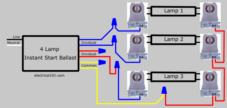
How To Replace 3 Lamp Parallel Ballasts Electrical 101

Universal Ballastar Energy Management B214pu115s50a 1 Or 2 Lamp
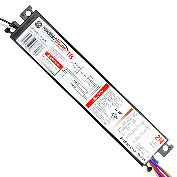
Ge 96714 T8 Fluorescent Ballast 120 277 Volt 1000bulbs Com

Ey 3029 Hid Philips Advance Ballast Wiring Diagram Wiring Diagram

You have in your house garage 120 240.
3 light 277 ballast wiring diagram. Its purpose is to show you step by step how to convert your current 4 foot t8 or t12 fluorescent tube light fixture to use the starled ballast. 120 phase to ground and 240 phase to phase. Fluorescent lamps use a ballast which transforms line voltage to a voltage to start up and operate the lamp s. 3 lamp rapid start ballast wiring diagram 2 ballasts one 2 lamp and one 1 lamp ballast.
The diagrams are categorized primarily according to the number of lamps in the. In commercial electrical wiring the authors state most larger commercial buildings utilize a 480 277 volt y connected service entrance. Wiring diagram how to bypass ballast for led tube. Newer fluorescent ballasts are usually rated for both 120 volts and 277 volts.
That s 277 to ground and 480 phase to phase hot to hot. Cut back additional wiring on opposite side of ballast as the led tube lamp only requires power at one end. It reveals the parts of the circuit as streamlined shapes and also the power and also signal connections between the gadgets. The emergency ballast wiring guide this document has been customized to contain a wide library of individual dia grams for various installation applications.
Some are rated for only 120 volts others for only 277 volts used in commercial environments. Check the ballest wiring diagram if they give you any alternatives. Universal voltage 120 277v workhorse ballast lamp compatibility charts wiring diagrams. Cfls for the home have a built in ballast at the base of.
Select the lamp quantity and wattage. Find wiring diagrams for your workhorse wham or longhorse ballasts. If a diagram cannot be found within this selection consult customer service. 7 14 2014 4 57 36 pm.
Electrical discharge lighting is designed to run on 277 volt wiring. Select your lamp type from the list below. Those are setup for a facility that has 277 480 volt 3 phase service. Assortment of 277 volt ballast wiring diagram.
Remove the ballast from the. 3 lamp series parallel ballast wiring diagramif one lamp fails or is removed in the series connected section then all lamps in that section will turn off but the lamps in the parallel circuit remain on. A wiring diagram is a simplified conventional photographic depiction of an electric circuit. A wiring diagram is a simplified standard pictorial representation of an electric circuit.
No way to get a 277 volt ballast to strike a lamp at 120 volts.

20 Complex Led Tube Wiring Diagram References Led Fluorescent

Fluorescent Ballast For T 8 32watt 2 Lamp Dual Voltage 120 277
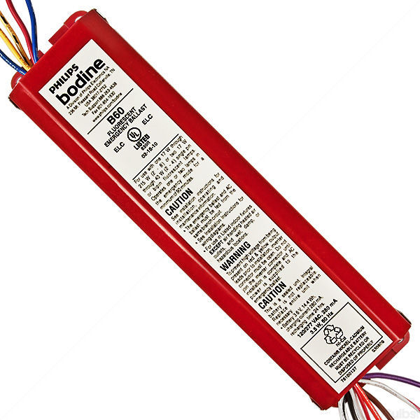
90 Min Backup Emergency Ballast Bodine B60 1000bulbs Com

Accupro Electronic Ballast Model Aprs232is120 Akrs232is120

Ge 120 To 277 Volt Ultrastart Program Start Electronic Ballast For

Lutron Ec3dt4mwku1s Cfl Dim Ballast T4 4 Pin 120 277v 1 Lamp

Led Fluorescent Tube Wiring Diagram Led Tubes Led Fluorescent

This Led Emergency Ballast Installs Within The T5 T8 Lighting

Ge 120 To 277 Volt Electronic Ballast For Hi Output 8 Ft 2 Lamp

120 To 277 Volt Electronic Ballast For 4 Ft 2 Lamp T12 Fixture

Ge Lighting 72277 Ge232mv N Diy Electronic 2 Lamp Ballast 72275

Fulham 128 Watt 120 Volt Fluorescent Electronic Ballast Fulham

Seven Things You Need To Know About Fluorescent Light Electronic
