3 Phase Multi Tap Transformer Connection Diagram Wiring

Multi Speed 3 Phase Motor 3 Speeds 1 Direction Power Control Diagrams

Three Phase Electrical Wiring Diagram Transfer Switch Circuit Diagram Electrical Circuit Diagram

How To Wire A Multi Tap Transformer Functional Devices Inc

3 Phase Wiring Diagram For House With Images Electrical Circuit Diagram Air Conditioning System Basic Electrical Wiring
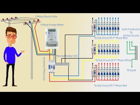
3 Phase Line Wiring Installation Single Phase Line In House House Wiring Earthbondhon Youtube
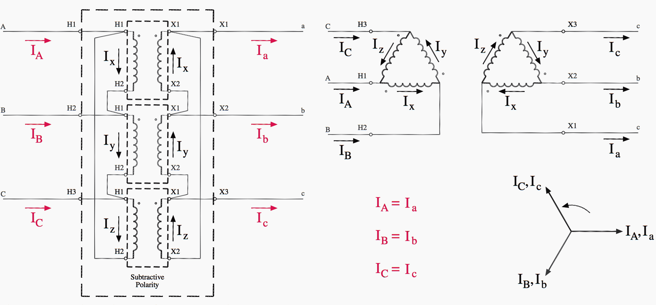
Easy Understanding Of 3 Phase Transformer Connections Delta Delta Wye Wye Delta Wye And Wye Delta Eep

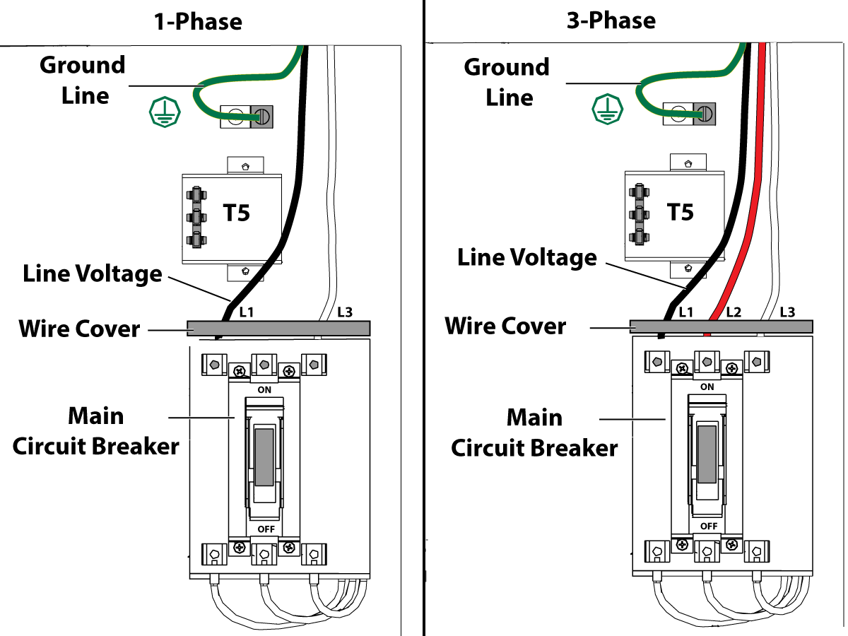
480 to 120 240 transformer wiring 06 04 2019 06 04 2019 2 comments on 480 to 120 240 transformer wiring a volt primary transformer with a volt secondary is operated at volts regardless of whether the source is three phase 3 wire or three phase 4 wire.
3 phase multi tap transformer connection diagram wiring. Jefferson electric transformer while three phase devices are usually the more cost effective option the single phase option provides more versatility and can be attractive from a reliability and maintenance standpoint. Three phase wiring diagrams always use wiring diagram supplied on motor nameplate. W2 cj2 ui vi wi w2 cj2 ui vi wi a cow voltage y high voltage z t4 til t12 10 til t4 t5 ali l2. The banking of these units results in a 240 120v 3 phase 4 wire secondary.
Note how a center tap terminal is used on the secondary of one transformer to ground the entire system. Then you would either connect phase a or c black or blue to the 120 vac tap on the transformer wht. Suitable for a three wire service or a four wire service with a mid tap ground. Different regions may use different voltages.
Although these systems may seem intimidating at first a walkthrough on 3 phase wiring for dummies will help clarify the whole situation. 1 3 i l of the line current where i l is the line current. Single phase wiring diagrams always use wiring diagram supplied on motor nameplate. The three phase rating of the transformer is also substantially reduced.
Here three 4 160v single phase transformers are needed with their primaries connected in series. Typical controller markings typical elementary diagram table 4 control and power connections for across the line starters 600 v or less from nema standard ics 2 321a 60 1 phase 2 phase 4 wire 3 phase line markings l1 l2 l1 l3. Phase 1 l2 l4. One disadvantage of delta connected three phase transformers is that each transformer must be wound for the full line voltage in our example above 100v and for.
When using the tap for single phase circuits the single phase load kva should not exceed 5 of the three phase kva rating of the transformer. If you wanted to use 240 vac on the primary you would take any two of the three phases and connect them to the orange and black wires on the transformer. They can also be found in large residential complexes and appliances requiring a large amount of power. 2 5 bnfc x1 h1 x2 x3 h2 h3 x0 3 2 1 3 2 1 3 2 1 connectconnect primary primary inter secondary.
Easy understanding of 3 phase transformer connections delta delta wye wye delta wye and wye delta on photo. Three phase systems are extremely common in industrial and commercial settings. Phase 2 l1 l2 l3 ground when used l1 is always ungrounded l2 motor running overcurrent.

3 Phase Electrical Wiring Installation In A Multi Story Building Jpg 663 1024 Electrical Wiring House Wiring
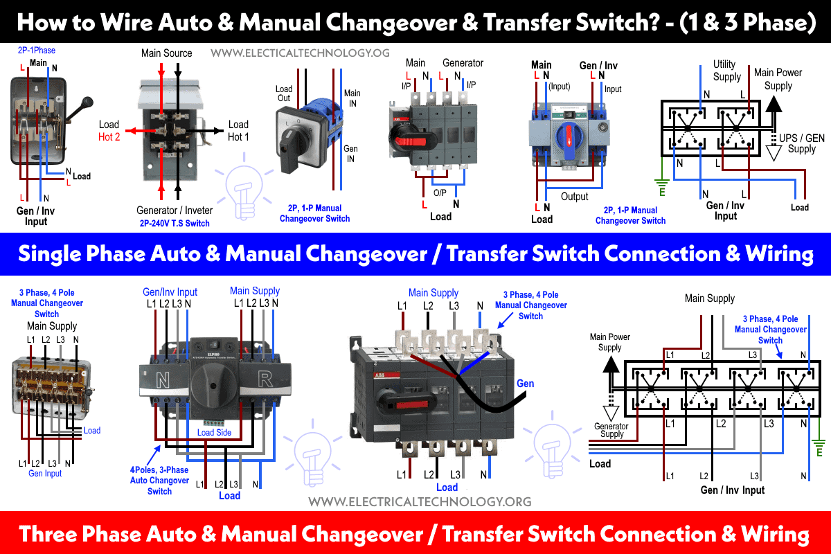
How To Wire Auto Manual Changeover Transfer Switch 1 3 Phase

47 Ways To Wire Your Power Meter Wrong Kele Com

New Wiring Diagram Three Phase Generator Diagram Diagramsample Diagramtemplate Wiringdiagram Diagramchar Diagram Electrical Diagram Home Electrical Wiring

Multi Speed 3 Phase Motor 3 Speeds 1 Direction Power Control Diagrams Electrical Circuit Diagram Electrical Projects Power Supply Design

Basic Parts Of A Single Phase Pole Mounted Distribution Transformers With Images Electrical Transformers Electrical Engineering Transformers

Three Phase Ac Generator Working Principle Multi Pole Diesel Alternators Hd 3d Ani With Images Transformers Electronic Engineering Electrical Engineering Technology

Two Speeds Two Directions Multispeed 3 Phase Motor Power Control Diagrams With Images Electrical Circuit Diagram Power Electricity
Installation Electrical Connection

Tap Changing Transformers With Images Transformers Tap Online

Resultado De Imagen Para 3 Phase Wire Connection Met Afbeeldingen Elektrische Bedrading Elektrotechniek Elektriciteit

Rev For Three Phase Motor Connection Power And Control Diagrams Electrical Circuit Diagram Electrical Wiring Diagram Electrical Symbols

Unique Wiring Diagram Design Sample Free Download Diagrams Digramssample Diagramimages Check More At Https Nostoc Co Wiring Diagram Design With Images Electrical Wiring
