Logic Diagram Of 4 Bit Ripple Counter
Ripple Counter Circuit Diagram Timing Diagram And Applications

4024 7 Bit Ripple Counter Displays

Ripple Counter

Synchronous Counter And The 4 Bit Synchronous Counter
Ripple Counter In Digital Logic Geeksforgeeks
Design 4 Bit Ripple Counter Using Negative Edge Triggered Jk Flip
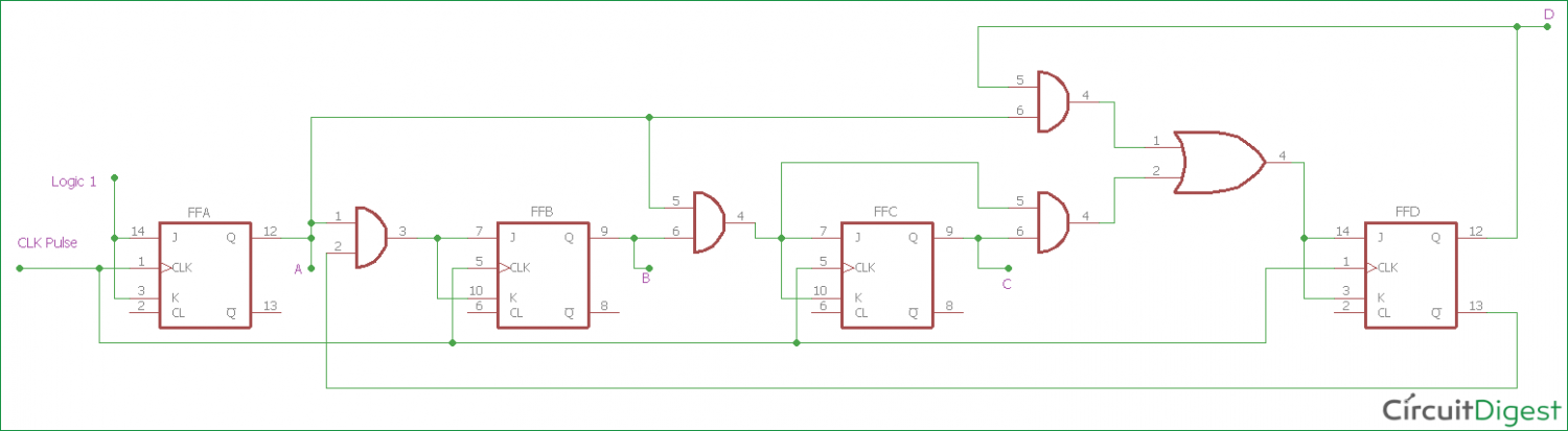
Therefore this type of counter is also known as a 4 bit synchronous up counter.
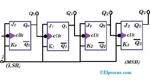
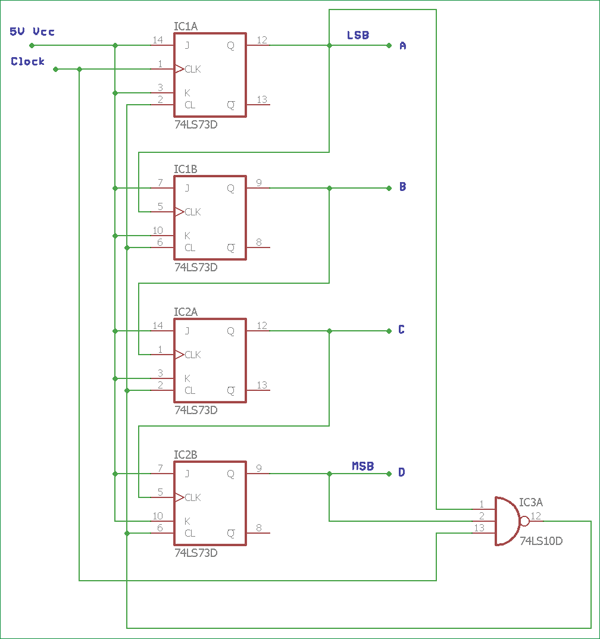
Logic diagram of 4 bit ripple counter. The toggle t flip flop are being used. The control signal functions of a 4 bit binary counter are given below where x is don t care the counter is connected as follows. Asynchronous or ripple counters. So they are elementary in design and also are less expensive.
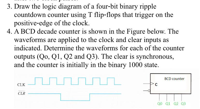
You are required to design a 4 bit even up counter using d flip flop by converting combinational circuit to sequential circuit. Because this 4 bit synchronous counter counts sequentially on every clock pulse the resulting outputs count upwards from 0 0000 to 15 1111. Draw the logic diagram of a four bit binary ripple countdown counter using a flip flops that trigger on the positive edge of the. But we can use the jk flip flop also with j and k connected permanently to logic 1.
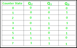
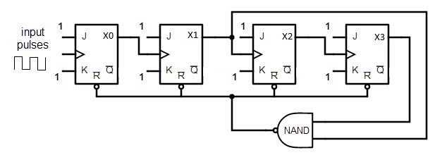
However we can easily construct a 4 bit synchronous down counter by connecting the and gates to the q output of the flip flops as shown to produce a waveform timing. The counter will only consider even inputs and the sequence of inputs will be 0 2 4 6 8 10 0. It is also known as mod n counter. Ripple counter a n bit ripple counter can count up to 2 n states.
We can cascade two or more 4 bit ripple counter and configure each individual as divided by 16 or divided by 8 formations to get mod 128 or more specified counter. Asynchronous or ripple counters. If the counter starts at 0 then it cycles through the following sequence. Please like share and subscribe to my channel.
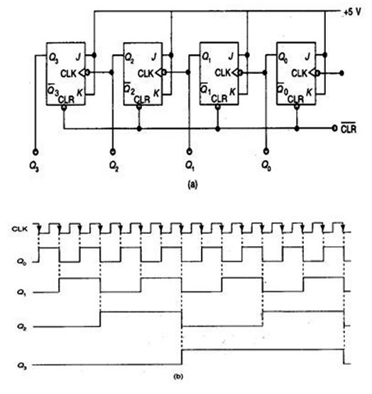
As a 3 bit ripple counter the input count pulses are applied. The logic diagram of a 2 bit ripple up counter is shown in figure. Assume that the counter and gate delays are negligible. But you can use the jk flip flop also with j and k connected permanently to logic 1.
In the 74ls segment 7493 ic could be configured in such way like if we configure 7493 as divided by 16 counter and cascade another 7493 chipsets as a. The input count pulses are applied to clock input cp0. The logic diagram of a 2 bit ripple up counter is shown in figure. A 0 3 4 b 0 3 4 5 c 0 1 2 3 4.
Simultaneous frequency divisions of 2 4 8 and 16 are performed at the q0 q1 q2 and q3 outputs as shown in the function table. The toggle t flip flop are being used. Asynchronous or ripple counters.

Ring Counter In Digital Logic Geeksforgeeks
Down Counter With Truncated Sequence 4 Bit Synchronous Decade
Asynchronous Counter Definition Working Truth Table Design
Decade Counter Bcd Counter

Counters Types Of Counters Binary Ripple Counter Ring Counter
Synchronous Counter Definition Working Truth Table Design
Https Inst Eecs Berkeley Edu Cs150 Sp13 Agenda Lec Lec22 Counters Pdf

Experiment Write Vhdl Code For Realize All Logic Gates Com Imagens
Ring Counters Johnson Ring Counter
Solved 3 Draw The Logic Diagram Of A Four Bit Binary Rip

Synchronouscounter Is One Whose Output Bits Change State
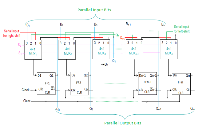
Universal Shift Register In Digital Logic Geeksforgeeks

10 Bit Ripple Counter Circuits
