Logic Diagram Of Mod 10 Counter

Mod Counters Are Truncated Modulus Counters

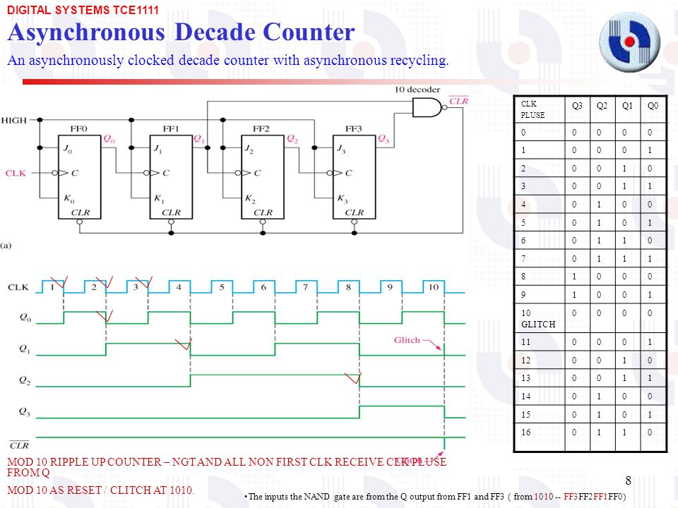
Asynchronous Counter As A Decade Counter

4 Mod10 Decade Or Bcd Asynchronous Up Counter Circuit

Schematics Com Mod 10 Up Counter Using Jk Flip Flops

F Alpha Net Experiment 5 Mod 10 Counter

Design Mod 10 Asynchronous Counter

We now have a decade or modulo 10 counter.
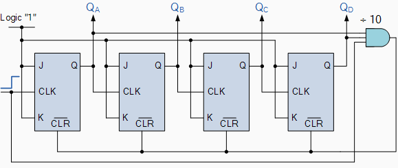
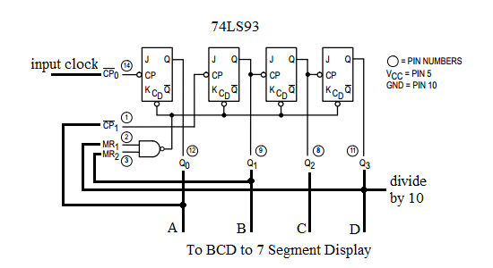
Logic diagram of mod 10 counter. So for example q a q b q c and q d the 74ls90 counting sequence is triggered on the negative going edge of the clock signal that is when the clock signal clk goes from logic 1 high to logic 0 low. In a mod 10 counter you are using a 4 bit counter that actually has 8 states. 74ls90 also have an independent toggle jk flip flop by clka and other three are driven by the clkb. You must be logged in to read the answer.
A standard binary counter can be converted to a decade decimal 10 counter with the aid of some additional logic to implement the desired state sequence. The mod 10 counter passes through 10 states before he starts anew and thus it is interesting when the decimal number system is used. Design mod 10 synchronous counter using jk flip flops check for the lock out condition if so how the lock out condition can be avoided. The logic diagram of a 2 bit ripple up counter is shown in figure.
It can be configured as a modulus 16 counter counts 0 15 by connecting the q 0 output back to the clk b input it can be configured as a modulus 10 counter decade by partial decoding of count 10 connect q 0 to clk b q 1 to ro 1 and q 3 to r0 2. But we can use the jk flip flop also with j and k connected permanently to logic 1. It consists of four master slave jk flip flop which are internally connected to provide mod 2 count to 2 counter and mod 5 counter. Counters are used in digital electronics for counting purpose they can count specific event happening in the circuit.
The counters four outputs are designated by the letter symbol q with a numeric subscript equal to the binary weight of the corresponding bit in the bcd counter circuits code. Draw the neat state diagram and circuit diagram with flip flops. 8 01x lect 24 rolling motion gyroscopes very non intuitive duration. The toggle t flip flop are being used.
It can be used as a divide by 2 counter by using only the first flip flop. According to wikipedia in digital logic and computing a counter is a device which stores and sometimes displays the number of times a particular event or process has occurred often in relationship to a clock signal. After reaching the count of 1001 the counter recycles back to 0000. In this video we learn mod 10 synchronous counter.
Experiment 5 the mod 10 counter a special place among counters has the mod 10 counter. Lectures by walter lewin. Decade 4 bit synchronous counter. Asynchronous or ripple counters.
Solved A Draw The State Diagram Of A Mod 10 Up Counter

Design Mod 10 Synchronous Counter Using Jk Flip Flops Check For
How To Design A Mod 10 Ripple Counter With D Flip Flops Quora
Counters
Https Www Studocu Com Tw Document National Taiwan University Lab For Electronics E2 85 B1 Lecture Notes Lab03 7 Segment Display And Mod 10 Counter1060320 2721898 View
Explain Asynchronous Decade Counter Computer Engineering

17 The Bcd Mod10 Synchronous Up Counter Circuit Constructed

Mod 10 Counter Decade Counter Easy Youtube
How To Design A Mod 10 Binary Up Counter Using Sr Flip Flops Quora
Asynchronous And Synchronous Counters Ppt Download
Tutorial Of Frequency Division

Synchronous Counter And The 4 Bit Synchronous Counter
12h 24h Digital Clock Circuit Online Digital Electronics Course