Low Temperature Defrost Timer Wiring Diagram Box

Wiring Thermostat For Attic Fan With Images Ceiling Fan Switch

Wiring Diagram For Ac Unit Elegant Goodman Condenser Wiring With

3 Phase Wiring Diagram For House With Images Central Heating

16 Stunning Wiring Diagram For 220 Volt Single Phase Motor
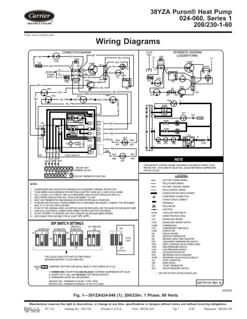
Wiring Diagrams Carrier

Split Air Conditioner Wiring Diagram With Images Refrigeration
Allied refrigeration 440 823 5720 cleveland ohio.
Low temperature defrost timer wiring diagram box. Pressure control boiler operating control used as a thermostat. The defrost timer board can then be mounted inside the snap track. Walk in freezer defrost timer wiring diagram autocardesign walk in freezer defrost timer wiring diagram free wiring commercial freezer defrost timer wiring wiring. The installation paper inside the snap track.
Modern refrigerators have a defrost function with a defrost timer thermostat heater and drain combined with an evaporator fan motor you may need to test your defrost timer at some point. Variety of walk in freezer defrost timer wiring diagram. Setpoints control initiation and termination. Yeah also lots of wiring layouts are provided this circuitry layout can swipe the visitor heart so much.
Step 1 understand what and where. Defrost defrost board db is a time and temperature control which includes a field selectable time period between checks for frost 30 50 and 90 minutes. Electronic timer and defrost cycle start only when contactor is energized and defrost thermostat dft is closed below 28 f 2 2 c. Like a clock this keeps the rhythm of defrosting and cooling going according to pre set time intervals.
Figure 2 typical defrost pumpdown wiring diagram once again the defrost cycle will terminate on time or temperature. The latest paragon defrost timer universal defrost timers udt works with multiple voltages removes built up of ice and frost easy to install simple to program part 9145 00 temp terminated part 9045 00 time terminated available as mechanism only without case add m to end of part number. The defrost timer board is wired to an 8ro board or the xm xr con troller outputs labeled dixell fan as shown in the following wiring diagram. Type of operation electrical rating refrigeration solenoid operation 120 240 v.
Beloved visitors when you are hunting the brand new freezer defrost timer wiring diagram electrical wiring diagram collection to read this day freezer defrost timer wiring diagram can be your referred electrical wiring representation. Refrigerator defrost timer wiring diagram image. Condenser fan cycling or typical line voltage wiring diagram.

Wiring Diagram For 220 Volt Air Compressor In 2020 With Images

10 General Electric Motor 5kc Wiring Diagram Wiring Diagram In

17 3 Phase Electric Water Heater Wiring Diagram Wiring Diagram

Honeywell Boiler Zone Valves Wiring Wiring 3 Zone With Honeywell
220 240 Wiring Diagram Instructions Dannychesnut Com

Split Air Conditioner Wiring Diagram Air Conditioner

Pin On Craftsman
Understanding Fridge Wiring Diagram Home Improvement Stack Exchange

W1 W2 E Hvac School

Pin On Hvac Air Conditioning

Hvac Water Chillers Principle Water Chillers Hvac Hvac Maintenance

New Wiring Diagram Kompresor Ac Diagram Diagramtemplate

Pin On Little House Electric
